In the world of discrete semiconductors, 2N7000 and
2N7002 are two of the most widely used N-channel enhancement-mode MOSFETs. Despite the similarity in naming, they exhibit notable differences in terms of key specifications, real-world performance, and application scenarios.
While the 2N7000, with its TO-92 through-hole package, has long been a favorite in prototyping and repair due to its ease of hand-soldering and robustness, the 2N7002 in SOT-23 SMD package reflects the modern pursuit of miniaturization and high integration, making it ideal for compact, high-performance PCB layouts.
Key Parameter Comparison
|
Parameter |
2N7000 |
2N7002 |
Notes |
|
Package |
TO-92 (Through-Hole) |
SOT-23 (Surface-Mount) |
2N7002 is smaller, ideal for high-density PCBs |
|
Maximum Drain Current (ID) |
200 mA |
300 mA |
2N7002 supports higher current |
|
Drain-Source Voltage (VDS) |
60 V |
60 V |
Same |
|
Gate Threshold Voltage (VGS(th)) |
0.8–3 V |
0.8–3 V |
Same |
|
On-Resistance (RDS(on)) |
5 Ω (VGS = 10 V) |
1.5 Ω (VGS = 10 V) |
2N7002 offers lower conduction loss |
|
Gate Charge (Qg) |
2.5 nC |
1.3 nC |
2N7002 enables faster switching |
|
Power Dissipation (PD) |
350 mW (TO-92) |
225 mW (SOT-23) |
2N7000 offers better heat dissipation |
2N7000: Suitable for prototyping, lab use, and simple circuits requiring manual soldering. Ideal for load currents under 200 mA.
2N7002: Preferred for compact PCB layouts, efficient 3.3V/5V systems, and high-frequency switching such as PWM dimming or motor control.
The 2N7000 can handle up to 200 mA continuous drain current, sufficient for driving LEDs, relays, power transistors, or acting as a signal amplifier in low-current applications.
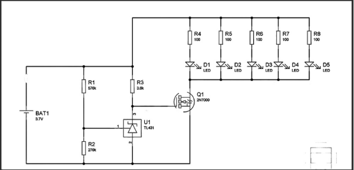
Example: LED flashlight circuit with battery protection
In this design, the 2N7000 acts as a low-side switch to drive a string of 5 LEDs (~100 mA total). When the TL431 reference voltage drops below 3.6V, the gate is turned off, thereby turning off the MOSFET and LEDs, providing under-voltage protection.
Example: Bidirectional Logic Level Converter Circuit
From MCU1 (5V) to MCU2 (3.3V):
-
When MCU1 TX is high (5V), the 2N7002 is off. Its drain (connected to MCU2 RX) is pulled up to 3.3V via a resistor.
-
When MCU1 TX is low (0V), the body diode conducts and pulls the 3.3V line low, allowing proper logic level communication.
From MCU2 (3.3V) to MCU1 (5V):
-
When MCU2 TX is high (3.3V), Vgs ≈ 0V, so the MOSFET remains off. The RX line on MCU1 is pulled up to 5V.
-
When MCU2 TX is low (0V), Vgs ≈ 3.3V, turning on the MOSFET, and the RX line on MCU1 is pulled low.

MCU1-MCU2
3.3V/5V Level Conversion Using 2N7002
✅ When to Choose 2N7002:
-
High-frequency switching (e.g., PWM, DC-DC converters)
-
SMD-compatible PCB designs (SOT-23 footprint)
-
Portable devices with space constraints
-
Low gate charge requirements (Qg ≈ 0.8 nC vs 2N7000's 2 nC)
✅ When to Choose 2N7000:
-
Higher voltage operations, up to 60V (with 20% margin)
-
Higher drain current needs (200 mA vs 115 mA for 2N7002)
-
Lower on-resistance sensitivity in low-voltage applications
-
Cost-sensitive volume production where through-hole is acceptable
Although both devices are N-channel MOSFETs and share a similar electrical nature, 2N7000 excels in robust, manually assembled circuits, while 2N7002 is tailored for modern compact, high-frequency SMD applications. Choosing the right device depends on your specific design goals, including power, frequency, space, and manufacturing process.